PON network requirements
With the rapid growth of security services and Internet of things, PON, as a low-cost and flexible means of large bandwidth transmission, has been more and more deployed in transmission access networks all over the world, and has the tendency to replace the traditional switch access network, especially in the scene of road monitoring and safe city, which covers a long distance Ideal and economical access mode.
02
Design of monitoring network transmission
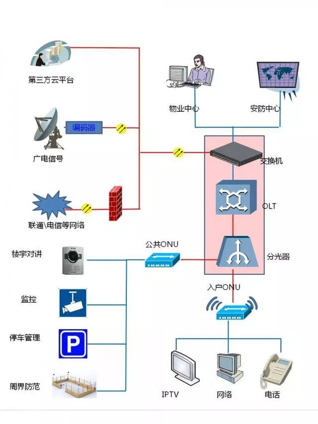
The main function of monitoring transmission network system is to access all kinds of monitoring resources, provide basic guarantee for the application of central management platform, and better serve all kinds of users. The network structure is shown in the figure below:
Network topology diagram
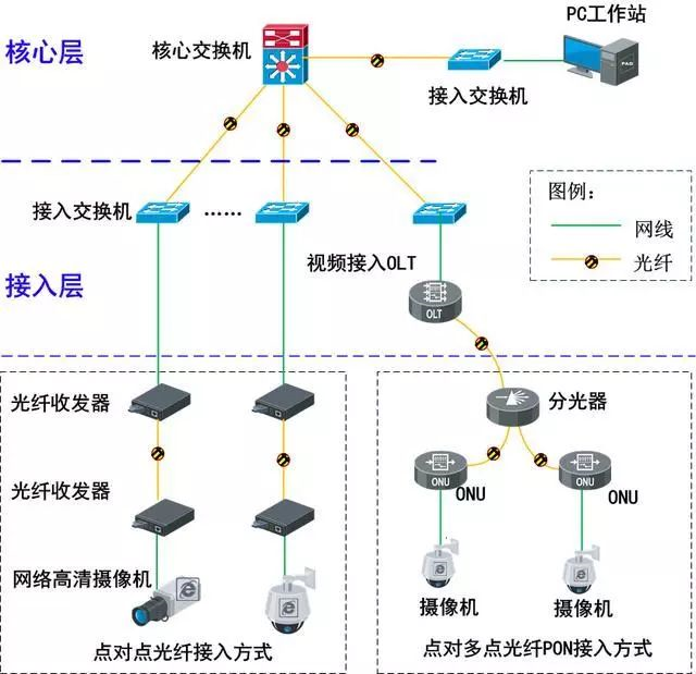
1) Core layer
Core network of data center
The main equipment of the core layer is the core switch. As the brain of the whole network, the configuration performance of the core switch is high. At present, the core switch generally has dual power supply and dual engine, so the core switch generally does not use the dual core switch deployment mode, but has higher requirements on the backplane bandwidth and processing capacity of the core switch.
2) Access layer
Front end video resource access
The front-end network uses independent IP address network segment to complete the interconnection of front-end monitoring devices. The front-end video resources are connected to the monitoring center or data room through IP transmission network for aggregation. At present, there are two common ways of front-end network access, usually point-to-point optical fiber access and point to multipoint PON access. The access layer needs to support the network access of NVR storage devices to ensure the network environment of NVR storage devices is safe and reliable.
User access
For the part of user access switch, the corresponding user access switch needs to be added to provide users with internet service. Access switches are deployed in the monitoring center to access the transmission network through 10 Gigabit / gigabit optical fiber links. Ensure the normal use of decoder and client in monitoring center
There is a two-level architecture in the network design, as shown in the figure below. The specific design is not described in detail here.
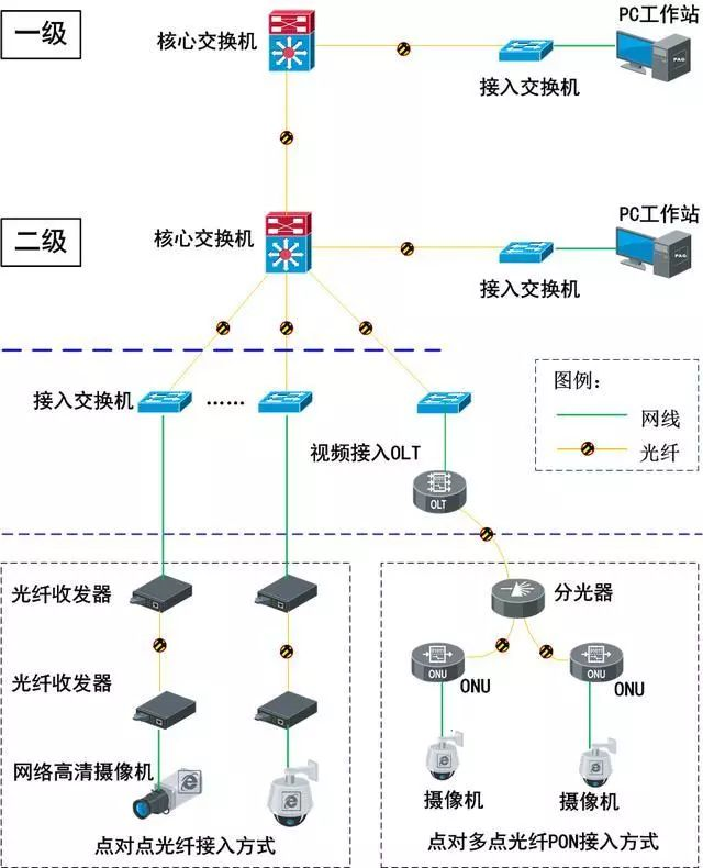
Secondary network structure design diagram
Network transmission bandwidth requirements
Considering the cost of network transmission process and other applications, the theoretical value of the available bandwidth of the link is about 80% of the link bandwidth. In order to ensure the high-quality transmission of video images, it is recommended to adopt the light load design when using the bandwidth, and the upper limit of the light load bandwidth should be controlled within 50% of the link bandwidth.
3) The network from the core layer switch to the access switch is transmitted by optical module, and the bandwidth needs to be more than Gigabit;
4) The bandwidth between transmission equipment such as optical fiber transceiver and access switch is recommended to reach 100 MB;
5) The transmission bandwidth between transmission equipment such as optical fiber transceiver is recommended to reach 100 MB;
Networking Scheme
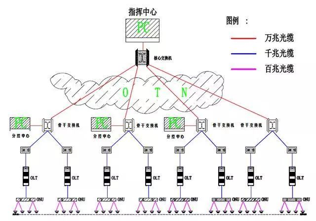
The video monitoring project uses 10 Gigabit backbone ring network and Gigabit convergence access to build a three-level image private network system. Through distributed video access and storage, digital video monitoring points are built.
The front end uses high-definition network camera for digital video acquisition, and transmits video to the sub control center through PON optical fiber link for unified access.
As a three-level node of the network, the sub control center is responsible for all front-end video access to the digital video private network. An integrated network video storage system integrating video monitoring system and storage system is deployed in the sub control center to access, store and forward digital video, and store images for 30 days.
As the core node of the network, the control center is responsible for the real-time video call of the whole network and the real-time monitoring of key monitoring points. As the core management node of video business, the control center deploys the video management platform to carry out centralized and unified authorization, maintenance and management for the equipment and users of the whole network.
The topology is as follows: (PON)
03
What are the advantages of passive optical network for monitoring system
1. PON equipment network planning - OLT deployment. In the early stage of xpon construction, centralized setting should be adopted, and OLT nodes should be set in the transmission sink node to cover scattered users in a certain area. In the mature period of xpon application, the principle of decentralized setting should be adopted. The OLT should be set in the machine room of wired access point or wireless access point with better conditions, and the transition should be gradually made to the unification of access network access and wireless access point, so as to fully realize the comprehensive utilization of basic resources. Large capacity OLT equipment is adopted to make full use of the distance advantage of optical access, reduce the number of offices and reduce the maintenance cost.
2. PON equipment network planning - the deployment of optical splitter. Optical splitter: at present, PON can adopt two-level optical splitter to ensure the flexibility of deployment and full utilization of ports; when the user penetration increases, the two-level optical splitter is adjusted to one-level optical splitter; at present, the access to PON network should adopt one-level optical splitter, and try not to exceed two-level optical splitter. When the user scale is small, the splitter should be set in a centralized way; when the user scale is large, the splitter can be set in a decentralized way, so as to be close to the user as much as possible. Location of light splitter: the light splitter can be placed in the junction box, community room, corridor and weak current well according to the actual situation of the project.
3. PON equipment network planning - ONU deployment. When building PON network to realize access network / FTTB, it is better to select the equipment with built-in voice module to realize integrated service access. ONU should be set according to the application mode and service requirements of FTTx network. For access network applications, ONU should be set in the user's home as far as possible, avoiding installation in the door or corridor. For ordinary public users, the ONU can be set in the smart box of the user terminal to provide protection, or placed on the desktop (using optical fiber information socket). For FTTB applications, ONU can be set in different positions such as cabinet in the building corridor or shaft, outdoor optical junction box, etc. In principle, ONU adopts local power supply mode instead of remote power supply mode. In order to ensure the normal development of voice service when the power is off, the backup power supply can be provided according to the battery module.
4. PON equipment network planning - network management. Centralized construction of manufacturer network management, open north interface, easy access to transmission integrated network management.